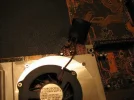
Hi guys, recently my A928 desknote fan went dead so i have to replace it, so can any of you guys who has opened up ur desknote can give me advice about the fan? is it easy to change it? do i have to completely disassemble the desknote and is it safe ? Thanks
Install the app
How to install the app on iOS
Follow along with the video below to see how to install our site as a web app on your home screen.
Note: This feature may not be available in some browsers.
You are using an out of date browser. It may not display this or other websites correctly.
You should upgrade or use an alternative browser.
You should upgrade or use an alternative browser.
i-Buddie 4 Desknote Review
- Thread starter Ian
- Start date
- Joined
- Jan 1, 2005
- Messages
- 76
- Reaction score
- 0
look at doddels post a few pages back, (37) can't get any better then thatKidstar said:Hi guys, recently my A928 desknote fan went dead so i have to replace it, so can any of you guys who has opened up ur desknote can give me advice about the fan? is it easy to change it? do i have to completely disassemble the desknote and is it safe ? Thanks
Luck
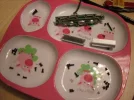
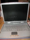
Pictures in case anyone who needs to DIY...(1/8)
Thanks to Vortex-5, I can't believe after 6 years I can still enjoy my Desknote - don't get me wrong, I am the lucky one, my A928 prong didn't melt until 4 months ago, so I did have it for a longer time than others, like people all around here.
Anyway, since it melt-down, I first thought about sending to David the man in Canada, but meantime I had a newborn which halted me for awhile. I finally get back to my life (aaarh.. baby and diapers, it drains all of you) and I decide to follow the instruction here (by Vortex-5), and others (https://www.pcreview.co.uk/forums/showthread.php?p=23198&highlight=panel#post23198)
It turned out pretty well, some screw numbers are not correct but almost perfect. I did write down how many screws I got from where. It helped me to re-build the unit back later easily.
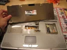
I have attached pictures here so it might give someone clear view of how-to.
(10 max. here at a time)
Good luck, guys, I found out it was pretty easy, but you take your own risk to do so!
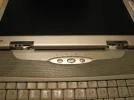
Please check by steps below - all the pictures are starting by doing LCD Panel, since all previous steps are pretty starightforward. You should use a good container to separate each section screws if possible.
Do your homework, write down the screw types, sizes, colors and numbers. They are in all kinds of different screws which definitely will screw you up later.
Thanks to Vortex-5, I can't believe after 6 years I can still enjoy my Desknote - don't get me wrong, I am the lucky one, my A928 prong didn't melt until 4 months ago, so I did have it for a longer time than others, like people all around here.
Anyway, since it melt-down, I first thought about sending to David the man in Canada, but meantime I had a newborn which halted me for awhile. I finally get back to my life (aaarh.. baby and diapers, it drains all of you) and I decide to follow the instruction here (by Vortex-5), and others (https://www.pcreview.co.uk/forums/showthread.php?p=23198&highlight=panel#post23198)
It turned out pretty well, some screw numbers are not correct but almost perfect. I did write down how many screws I got from where. It helped me to re-build the unit back later easily.
I have attached pictures here so it might give someone clear view of how-to.
(10 max. here at a time)
Good luck, guys, I found out it was pretty easy, but you take your own risk to do so!
Please check by steps below - all the pictures are starting by doing LCD Panel, since all previous steps are pretty starightforward. You should use a good container to separate each section screws if possible.
Do your homework, write down the screw types, sizes, colors and numbers. They are in all kinds of different screws which definitely will screw you up later.
Vortex-5 said:Ok I'll try to go throught all the screws that are in the laptop next time I open the laptop (haven't needed to in the last 1.5 years since the fix) I will take closer pictures.
We'll proceed around sections of the case in efforts to keep things simple
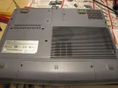
Around the Case Underside clockwiseStarting from the corner of the laptop closest to the stickerremove 1 screw from the corner proceed in a clockwise direction now
remove the 2 screws next to the usb ports
remove the 1 screw in the center (next to the svga port)
remove 2 screws next to the cpu port
remove 1 screw next to the IEEE1394 port
remove the final underside screw on the corner
Ram sectionremove 2 screws on the ram holder
under the ram cover remove 1 more screw under the metal ram shield
under that remove 2 more additional screws that attack to the case
CD-ROM Sectionremove the tree screws that hold the dvd-rom
remove the dvd-rom drive by sliding it out
remove 3 screws under the dvd-rom drive
Hard driveremove 2 screws from hard drive
remove hard drive
(can't remember if there where more screws here)
CPU SectionRemove 1 screw from the CPU cover (if your careful you don't need to remove the cpu)
otherwise remove the CPU but removing the 4 screws that hold it then unseat the CPU by flipping the switch store your CPU in a safe place it's sensitive!
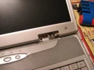
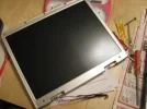
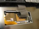
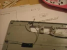
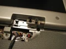
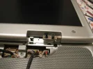
LCD PanelWARNING THIS MUST BE REMOVED VERY CAREFULLY
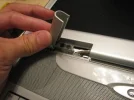
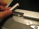
It is located at the bottom of the LCD panelUnclip the two clips you can do this by sticking a screw driver under the clips and slowly pry (very slowly from the side where the ports are)
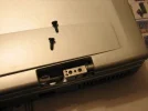
Once the clips are uncliped you have 4 screws under the panel to remove
Now uncover the plastic piece where your hard drive caps lock num lock indicators are
I forgot how many screws you can find underneath this section but be sure to uncover all of them
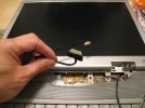
Remember to unplug both cables from the LCD panel before you attempt to separate the LCD
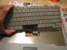
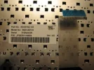
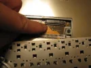
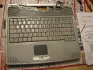
Keyboard SectionWARNING THIS ALSO MUST BE DONE BEFORE YOU ATTEMPT TO SEPARATE THE CASERight between the end and right cursorthere's a section you can pry to begin to release the keyboard.
Grab a paperclip and begin working your way along the bottom until you get to the space bar
DO NOT GO PAST THE SPACE BAR
There's a keyboard connector wire right where the space bar is if you go past it you might risk breaking it.
Take a philips screw driver and press against the clips to until you fully unseat the remainder of the keyboard.
Unclip the wire and remove the keyboard.MORE SCREWS YAY!
under the keyboard you will find 3 screws one of which is underneath a warranty void sticker.
At this point your laptop should be openable don't force it the laptop should open freely from what I remember.
Hope this helps post you have any more questions (you might need to pm or email me to get my attention).
Vortex-5
Attachments
-
 450.IMG00001.webp17.8 KB · Views: 350
 -
 450.IMG00005.webp35.2 KB · Views: 298
 -
 450.IMG00008.webp16 KB · Views: 263
 -
 450.IMG00012.webp30.3 KB · Views: 308
 -
 450.IMG00021.webp26.8 KB · Views: 291
 -
 450.IMG00024.webp38 KB · Views: 306
 -
 450.IMG00028.webp27.1 KB · Views: 306
 -
 450.IMG00031.webp25 KB · Views: 335
 -
 450.IMG00035.webp17.9 KB · Views: 295
 -
 450.IMG00045.webp28.2 KB · Views: 418
Last edited:
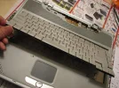
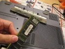
Pictures in case anyone who needs to DIY...(2/8)
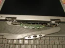
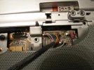
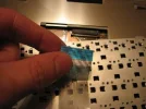
Be very careful when detatch keyboard. see the photo so you know how to avoid damage the wire.
Here are batch 2
Be very careful when detatch keyboard. see the photo so you know how to avoid damage the wire.
Here are batch 2
webtools said:Thanks to Vortex, I can't believe after 6 years I can still enjoy my Desknote - don't get me wrong, I am the lucky one, my A928 prong didn't melt until 4 months ago, so I did have it for a longer time than others, like people all around here.
Anyway, since it melt-down, I first thought about sending to David the man in Canada, but meantime I had a newborn which halted me for awhile. I finally get back to my life (aaarh.. baby and diapers, it drains all of you) and I decide to follow the instruction here (by Vortex), and others (https://www.pcreview.co.uk/forums/showthread.php?p=23198&highlight=panel#post23198)
It turned out pretty well, some screw numbers are not correct but almost perfect. I did write down how many screws I got from where. It helped me to re-build the unit back later easily.
I have attached pictures here so it might give someone clear view of how-to.
(10 max. here at a time)
Good luck, guys, I found out it was pretty easy, but you take your own risk to do so!
Attachments
-
 450.IMG00046.webp19.7 KB · Views: 256
 -
 450.IMG00049.webp27.2 KB · Views: 384
 -
 450.IMG00051.webp18.3 KB · Views: 311
 -
 450.IMG00052.webp21.7 KB · Views: 219
 -
 450.IMG00058.webp30.4 KB · Views: 360
 -
 450.IMG00063.webp31.8 KB · Views: 279
 -
 450.IMG00075.webp15.8 KB · Views: 259
 -
 450.IMG00079.webp17.1 KB · Views: 271
 -
 450.IMG00081.webp14.1 KB · Views: 260
 -
 450.IMG00094.webp56.4 KB · Views: 669
Last edited:
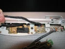
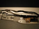
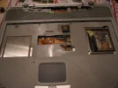
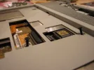
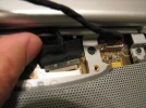
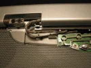
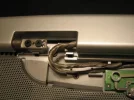
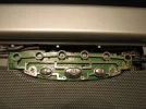
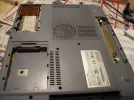
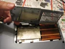
Pictures in case anyone who needs to DIY...(3/8)
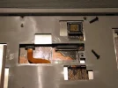
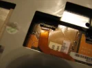
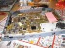
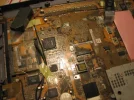
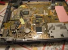
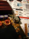
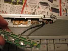
By this time, you have to find out ANY hiddenr screws - they are mostly in silver, and take the printer/monitor screws out as well.
After taking these screws you should be able to take the motherboard out. The power plug is under so you have to turn it upside down.
You have to take the heatsink out as well.
Mine, the 3rd plug, is losen!! The solder melt to the bottom and left the ping untouched.
I am luckyly enough it did not swing, so I just have to solder it back, no pictures taken at this point.... too stress!!! haha............ I put the other side of the mother board 20 degree higher, so the solder at the bottom end can "flow back" to the ping position. It works well.
Here are batch 3
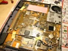
Attachments
-
 450.IMG00097.webp39 KB · Views: 288
 -
 450.IMG00099.webp38.1 KB · Views: 318
 -
 450.IMG00102.webp48.7 KB · Views: 2,517
 -
 450.IMG00105.webp51.4 KB · Views: 267
 -
 450.IMG00108.webp47.1 KB · Views: 326
 -
 450.IMG00113.webp31.6 KB · Views: 317
 -
 450.IMG00115.webp30.8 KB · Views: 250
 -
 450.IMG00120.webp36 KB · Views: 281
 -
 450.IMG00134.webp34 KB · Views: 286
 -
 450.IMG00136.webp57.2 KB · Views: 298
Last edited:
Pictures in case anyone who needs to DIY...(4/8)
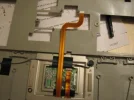
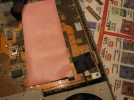
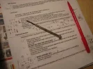
I wrote down all necessary info (screws, basically!) to make sure I won't have problem later.....
so after the solder done, I felt I was so happy and found out this desknote is really nice designed (by that time)! Well I don't mean the power system design! That's the point.
Here are batch 4
I wrote down all necessary info (screws, basically!) to make sure I won't have problem later.....
so after the solder done, I felt I was so happy and found out this desknote is really nice designed (by that time)! Well I don't mean the power system design! That's the point.
Here are batch 4
Attachments
-
 450.IMG00138.webp34.3 KB · Views: 218
 -
 450.IMG00139.webp24.5 KB · Views: 241
 -
 450.IMG00140.webp25.2 KB · Views: 269
 -
 450.IMG00144.webp25.6 KB · Views: 243
 -
 450.IMG00147.webp20.8 KB · Views: 245
 -
 450.IMG00151.webp19.3 KB · Views: 243
 -
 450.IMG00156.webp36.3 KB · Views: 739
 -
 450.IMG00161.webp24.2 KB · Views: 217
 -
 450.IMG00162.webp44.3 KB · Views: 292
 -
 450.IMG00163.webp37.8 KB · Views: 210
Last edited:
Pictures in case anyone who needs to DIY...(5/8)
So, just carefully reverse all steps back! Make sure you have plug all cables back, of coourse.
Here are batch 5
So, just carefully reverse all steps back! Make sure you have plug all cables back, of coourse.
Here are batch 5
Attachments
-
 450.IMG00164.webp43.2 KB · Views: 232
 -
 450.IMG00174.webp32 KB · Views: 239
 -
 450.IMG00178.webp23.2 KB · Views: 218
 -
 450.IMG00180.webp30.5 KB · Views: 223
 -
 450.IMG00181.webp30 KB · Views: 260
 -
 450.IMG00182.webp38.4 KB · Views: 234
 -
 450.IMG00183.webp27.7 KB · Views: 244
 -
 450.IMG00184.webp29.7 KB · Views: 249
 -
 450.IMG00187.webp22.7 KB · Views: 286
 -
 450.IMG00189.webp39.9 KB · Views: 233
Last edited:
Pictures in case anyone who needs to DIY...(6/8)
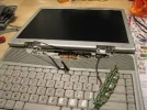
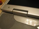
Mainly the LCD, even I was putting things back, you can still find this useful if you are taking it apart.
Here are batch 6
Mainly the LCD, even I was putting things back, you can still find this useful if you are taking it apart.
Here are batch 6
Attachments
-
 450.IMG00192.webp33 KB · Views: 240
 -
 450.IMG00193.webp24.3 KB · Views: 221
 -
 450.IMG00194.webp36.3 KB · Views: 226
 -
 450.IMG00195.webp27.2 KB · Views: 232
 -
 450.IMG00196.webp31.4 KB · Views: 238
 -
 450.IMG00198.webp28.2 KB · Views: 238
 -
 450.IMG00199.webp25.9 KB · Views: 227
 -
 450.IMG00202.webp32.9 KB · Views: 236
 -
 450.IMG00203.webp23.9 KB · Views: 237
 -
 450.IMG00205.webp28.8 KB · Views: 216
Last edited:
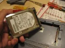
Pictures in case anyone who needs to DIY...(7/8)
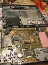
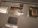
After the LCD is back to place, ha! You are 95% done!
Putting all the parts back now at the bottom.
Here are batch 7
After the LCD is back to place, ha! You are 95% done!
Putting all the parts back now at the bottom.
Here are batch 7
Attachments
-
 450.IMG00207.webp23.7 KB · Views: 220
 -
 450.IMG00208.webp26.4 KB · Views: 188
 -
 450.IMG00210.webp21.3 KB · Views: 233
 -
 450.IMG00213.webp32.9 KB · Views: 231
 -
 450.IMG00215.webp27.3 KB · Views: 221
 -
 450.IMG00217.webp32.8 KB · Views: 214
 -
 450.IMG00223.webp27.5 KB · Views: 234
 -
 450.IMG00225.webp17.1 KB · Views: 219
 -
 450.IMG00228.webp20 KB · Views: 243
 -
 450.IMG00230.webp25.8 KB · Views: 254
Last edited:
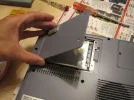
Pictures in case anyone who needs to DIY...(8/8)
After 3+ hours sitting by the table, now I have the last screws to take care.
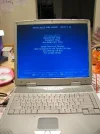
And I can't wait to see the moment of truth.......
Tada! It is back to life.
Hey did you see the screws.... even for the very bottom, there are at least 3 types, so, really do your homework, note which one goes where!
Here are batch 8
And you know what? Even I did all the homeworks, I now have 2 silver screws on hand and I have no idea where they should go. Man~~~ That's the price I have to pay.....
Good luck to all i-buddy buddies!
After 3+ hours sitting by the table, now I have the last screws to take care.
And I can't wait to see the moment of truth.......
Tada! It is back to life.
Hey did you see the screws.... even for the very bottom, there are at least 3 types, so, really do your homework, note which one goes where!
Here are batch 8
And you know what? Even I did all the homeworks, I now have 2 silver screws on hand and I have no idea where they should go. Man~~~ That's the price I have to pay.....
Good luck to all i-buddy buddies!
Attachments
-
 450.IMG00237.webp39 KB · Views: 249
 -
 450.IMG00239.webp28.7 KB · Views: 259
 -
 450.IMG00243.webp23.6 KB · Views: 229
 -
 450.IMG00244.webp23.2 KB · Views: 213
 -
 450.IMG00245.webp21.7 KB · Views: 257
 -
 450.IMG00246.webp13.9 KB · Views: 201
 -
 450.IMG00251.webp27.2 KB · Views: 302
 -
 450.IMG00253.webp25 KB · Views: 242
 -
 450.IMG00258.webp19.3 KB · Views: 247
Last edited:
CMOS battery replacement
I have the Deskbook laptop A928A by Cybermed computer in California. I think that it is actually the I Buddie.
I get a message on the screen every once in a while to change the CMOS battery. I called Cybermed, but they don't even remember the computer. Is the battery something that can be changed fairly easily?
TTP
ttp said:I have the Deskbook laptop A928A by Cybermed computer in California. I think that it is actually the I Buddie.
I get a message on the screen every once in a while to change the CMOS battery. I called Cybermed, but they don't even remember the computer. Is the battery something that can be changed fairly easily?
TTP
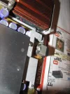
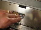
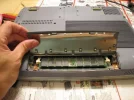
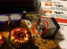
See the battery?
Does that answer you?
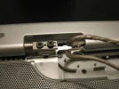
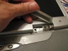
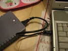
I've seen several notebooks with the same issue - a defective, melted and burned power jack (and plug) on their ECS A928 "Desknote" laptop.
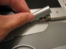
To solve the problem, the low quality original jack was removed and replaced with a MUCH more common (and reliable!) type of power jack. The original power adapter end was also replaced with a matching standard plug.
The new jack is rated for 6+ amps, and is the same industry-standard connector used on MANY notebooks - a 5.5mm (outer) / 2.5mm (inner) center-positive power plug.
I wish I'd snapped a few pictures. Next time one of these is our shop, I'll take a few "before" and "after" shots and post them here.
If you're adept with a soldering iron and comfortable tearing apart your notebook, send me a PM or email. I'll show you the specific jack that can be securely installed as a permanent replacement with a little work.
If you're in the US and have this same problem, my employer has a flat price on all laptop power jack repairs. Sorry, they don't currently offer services outside the US.
A. Woolf
www.notebookmechanix.com
P.S. Resoldering the same overheated and corroded power plug is a short term fix at best. replace the jack, unless you want to be tearing the notebook back apart again (and again).
Disclaimer:
Views and Opinions expressed here are my own and do not necessarily represent the views and opinion of my employer.
Last edited:
Hi awoolf, thanks for showing up.
Could you please let us know which is the specific jack you're mentioning? I've seen a lot of 5.5mm (outer) / 2.5mm (inner) but most are rated at about 3A. Never came across a 5.5mm/2.5mm rated at 6+Amps yet. Hopefully you can help us out!
Thank you once again.
Could you please let us know which is the specific jack you're mentioning? I've seen a lot of 5.5mm (outer) / 2.5mm (inner) but most are rated at about 3A. Never came across a 5.5mm/2.5mm rated at 6+Amps yet. Hopefully you can help us out!
Thank you once again.
Doddel, thank you so much for your reply at page 41 and your instructions at
https://www.pcreview.co.uk/forums/showpost.php?p=8829769&postcount=360
Sorry I haven't replied yet, I did forget about my ECS for a while. Mostly because I had no luck in finiding the capacitors you mentionned.
I couldn't send you a private message because I don't have enough posts on this board yet.
Anyone knows where those exact capacitors can be found on the net, I'm in South America...
Here's what Doddel says:
"* 1 uF, 5V tantalum capacitor parallel to C458, next to the max1632
* 3 pcs. 0.22 uF capacitors in positions C200, C201, C202 (were not present; to be found at the back of the six electrolytes)
* mount C152, 86 uF, 22V, plus towards processor"
One thing I didn't quite understand since I haven't taken the motherboard out is when you say: "mount C152, 86 uF, 22V, plus towards processor".
Do you mean that there's already a 86uF 22V capacitator mounted at position C152 that has to be unmounted then re-mounted with the plus sign oriented towards the processor? Or did you mount a previously missing capacitator at C152?
Thanks a lot for any help.
- Joined
- Jan 1, 2005
- Messages
- 76
- Reaction score
- 0
good deal on a 2.8/512/400 SL7EY processor
http://cgi.ebay.com/ws/eBayISAPI.dl...loc=closed_view_item&refwidgettype=osi_widget
http://cgi.ebay.com/ws/eBayISAPI.dl...loc=closed_view_item&refwidgettype=osi_widget
same old power supply probelms for the desknote, same surefire solution - david cai ( (e-mail address removed) ) tested the fix once i got my computer back (it was ready to ship back to me one day after he got it ) by leaving the computer running for 72 hours straight and the plug never overheated (used to smell burnt rubber after only 90 minutes )
It looks like laptopjacks.com now carries the original power jack for the A928, A929, i-Buddie, etc. Their part number is DN171111 and they sell it for $25(US). (I have no affiliation with LaptopJacks.com)
Laptopjacks P/N TS71525 appears identical to the jack we modify for use in these ECS notebooks. After looking at the mfgr's spec sheet, the jack we carry is rated for a whopping 10A at 20V. Laptopjacks does not give any specs, but we can assume it is good for at least the 6A that many Toshibas require. (where this jack is commonly used)
If anyone in the US is not comfortable opening/modifying their laptop, www.notebookmechanix.com offers a flat rate power jack repair service.
A. Woolf
www.notebookmechanix.com
Disclaimer:
Views and opinions expressed here are my own and do not necessarily represent the views and opinion of my employer.
Last edited:
Ask a Question
Want to reply to this thread or ask your own question?
You'll need to choose a username for the site, which only take a couple of moments. After that, you can post your question and our members will help you out.